
Hemisphere Solar Tracker Assembly
I. PREPARATION
- These are the same files listed on the previous page. We have provided a link on this page as well, for your convenience.
- If you need to see more detail on any of the photos, right click the photo with your mouse. Select the "Open image in new tab" option.
A. 3D print the parts
There are 3 parts to print. The main part will take close to 2 hours to print. The other two parts will about take 10 minutes each. Original FreeCAD file
Download the STL Files and print them with these settings. It is recommended to print them all separately rather than as one large print.
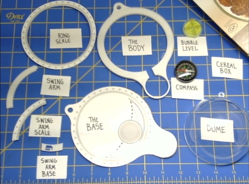
- 3D Print the Body of the Sun Tracker: HemisphereSolarTrackerMini-Body.stl
- 1.9 Hours of printing
- No support, skirt adhesion.
- 3D Print the Swing Arm: HemisphereSolarTrackerMini-SwingArm.stl
- 10 min of printing
- No support, skirt Adhesion.
- 3D Print the Swing Arm Base: HemisphereSolarTrackerMini-SwingArmBase.stl
- 10 min of printing
- No support, Skirt Adhesion
B. Print and Cut the Scales.
Print PDF Versions of Scales on Vinyl Paper or Photo Paper
- Print the Body piece: HemisphereSolarTrackerMini_Artwork-Body_PRINT.pdf
- Cut the piece on your Paper Cutting Machine: HemisphereSolarTrackerMini_Artwork-Body_CUT.pdf
- Print the Protractor piece and Swing Arm Scale: HemisphereSolarTrackerMini_Artwork-Protractor_PRINT.pdf
- Cut the piece on your Paper Cutting Machine: HemisphereSolarTrackerMini_Artwork-Protractor_CUT.pdf
C. Spray the paper with UV Fixture spray
- Use Krylon UV-Resistant Clear spray. We recommend spraying the printed Photo Paper/Vinyl Paper 3 times. Be sure each layer is dry before applying the next one.

II. ASSEMBLE THE BASE
-
Gather the cardboard, the photo paper or vinyl paper that has been printed, scissors and an Exacto knife.
-
A. Choose whether you're using printed Vinyl Paper or printed Photo Paper
Option 1: Using printed Vinyl Paper

Stick the vinyl printed Base to the cardboard.
- After printing the Base on vinyl, cut it in your craft cutter.
- OR cut it by hand.
- Peel the Base off the vinyl sheet.

- Carefully stick it to the cardboard.


- Use scissors to cut the cardboard in the shape of the Base.

- Cut the small tripod mounting hole out of the cardboard, using the Exacto.

- Now, skip down to the Assembly part of the instructions.
Option 2: Using Contact Cement/Hot Glue
- We will be showing you how to use Contact Cement. Hot Glue is easier and does not require a demonstration. Note that everywhere I say "contact cement," you can mentally replace that with "Hot Glue."
- Gather the parts; cardboard, the printed Base, the 3D printed Body, a technician Q-tip, Fine tip Sharpie, Scissors, Contact Cement, and an Exacto (not shown).

Prepare the bottom of the Base
- Cut out a rectangle from your cardboard.
- Place the 3D printed Body piece on to the cardboard.

- Use a pen to outline the shape of the base.

Glue the Base
Glue the Base to the cardboard, using Contact Cement.
- Apply Contact Cement to the area inside the outline on the cardboard.

- Apply Contact Cement to the back of the printed Base, using a Technician's Q-tip.

- Wait 15 - 20 minutes for the glue to dry.

- Stick the two pieces together.

- Pat yourself on the back for a job well done!

- Cut the glued pieces out of the cardboard, using scissors.

- Cut the small hole out of the cardboard, using the Exacto.
B. Adding the 3D Printed Body
- Gather the Contact Cement/Hot Glue, Technician's Q-tip, the Base, the 3D printed Body.

- You will be applying the Contact Cement to the edge of the printed side of the base, and to the back side of the 3D printed Body. To see the areas that will need glue, place the 3D printed Body on top of the Base to figure out where the glue will go.

- Apply Contact Cement to printed side of the Base, using a Technician's Q-tip. Place the glue along the edge of the Base. Cover the protractor completely. The protractor is the dial part with the numbers.

Remember DO NOT fill in the area under thin ring of the 3D printed Body. Just put a little glue along the edge that will be underneath the 3D printed rim.

- Apply Contact Cement to the back of the 3D printed Body, using a Technician's Q-tip. The front of the 3D printed body has a lip on it. This is the front - DO NOT put glue on this side, yet.

- Apply the glue to THIS side, the side WITHOUT the lip.

- Wait 15 - 20 minutes for the glue to dry.
- Line up the two pieces, so that the edges of the small ring look like this:

- Stick the two pieces together.

III. ASSEMBLY
- Gather the assembled Base, the compass, the bubble level and a Hot Glue Gun for this next part.

A. Add the Bubble Level and the Compass
- Use Hot Glue to attach the Bubble Level to the Base, in the printed circle.
- Use Hot Glue to attach the Compass to the Base, in the 3D printed circle.

B. Add the Ring Scale
- Select the proper side of your Globe. The Globe has two parts.

- The side we want to use has the tab that is flush with the bottom of the Globe.

Option 1:
Add the Ring Scale to the Base with the printed vinyl paper.
- Place the Globe onto the Base. Place the tab of the Globe into the slot on the Base.

- Peel up the Ring Scale from the vinyl.

- Orient the numbers on the Ring Scale, so that the number "0" faces the compass.

- Stick the vinyl onto the Body. The center of the Bubble Level, should align with the "0" on the Ring Scale, which should align with "S" on the compass.

Option 2:
Add the Ring Scale to the Base with Contact Cement. * Get the following supplies to complete this next part; Contact Cement, Technician Q-tip, the Dome, the Base, and the Photo Paper Ring Scale.

- Place the Globe onto the Base.

- Apply Contact Cement to the back of the Ring Scale, using a Technician's Q-tip.
- Apply Contact Cement to 3D printed ring of the Base, using a Technician's Q-tip.
- Wait 15 - 20 minutes for the glue to dry.
- Place the Photo Paper Ring Scale onto the 3D printed Ring Scale.
- Orient the numbers on the Ring Scale, so that the number "O" faces the compass.
- Stick the two pieces together.
C. Add the Swing Arm Scale to the Swing Arm.
- Get the following supplies to complete this next part; Contact Cement/Hot Glue, Technician Q-tip, the 3D printed Swing Arm, the Swing Arm Scale (on photo paper or vinyl).

- If you are using vinyl printed photo paper, simply stick it to 3D printed the Swing Arm Scale. Click the end of the 3D printed Swing Arm into the hole of the 3D printed Swing Arm Base. Congratulations! Now you can move to Step IV.
D. Attach Swing Arm
Using Contact Cement/Hot Glue to attach the Swing Arm Scale
- Apply Contact Cement to the back of the Swing Arm Scale, using a Technician's Q-tip.
- Apply Contact Cement to 3D printed Swing Arm, using a Technician's Q-tip.
- Wait 15 - 20 minutes for the glue to dry.
- Stick the two pieces together.
- Attach the foot of the Swing Arm Scale by pushing it into the foot.

- Congratulations! You now have a working Hemisphere Solar Tracker!

- But you're not done yet! You will need to mount it on a tripod to make it easier to use.
IV. Attach to Tripod
ATTACH THE HEMISPHERE SOLAR TRACKER TO THE TRIPOD
- Gather your tripod, silver Sharpie (not shown), one 1/4" x 1" bolt and two 1/4" nuts.

A. Prepare the Tripod
- Remove the Quick-Release plate on the top of the tripod. Mark a spot in the center of the Quick-Release plate holder. It is shown here with the light colored dot.

B. Drill the Hole
- Using a 15/64" drill bit, drill a hole in the Quick-Release plate holder on the tripod. Don't panic if you don't have this specific drill bit. A 1/4" drill bit should work if you use it to ream the hole to a bigger size.

- Here is the hole after drilling.

C. Attach the Hemisphere Solar Tracker
- Put a 1/4 x 1" bolt through the tripod hole.

- Put the 1/4" nut onto the bolt.

- Place the tripod hole of the Hemisphere Solar Tracker over the bolt and secure it with the second 1/4" nut.

Now, you're ready for action!
